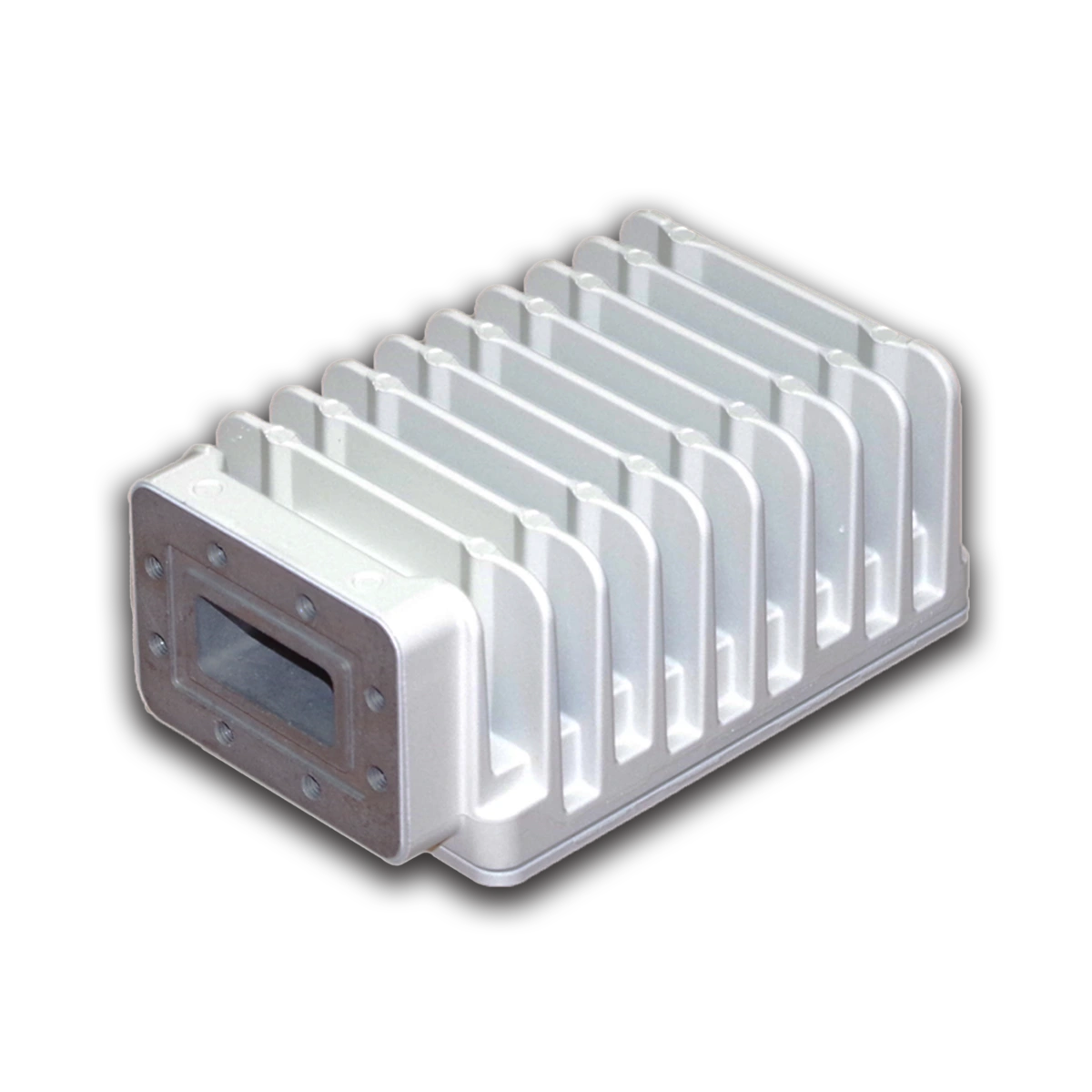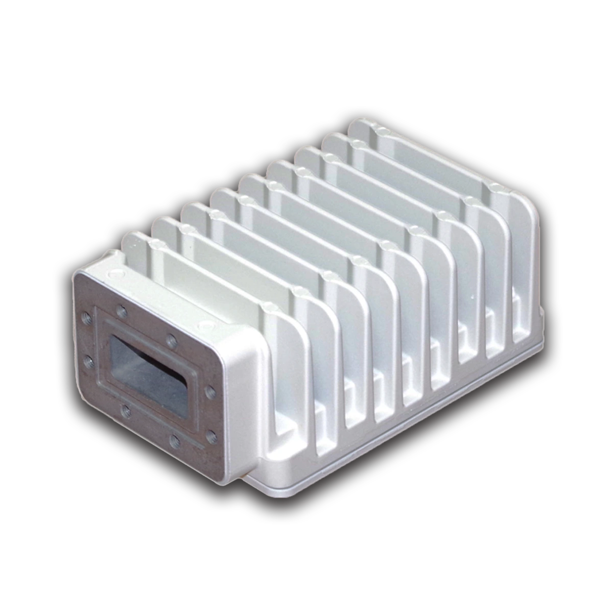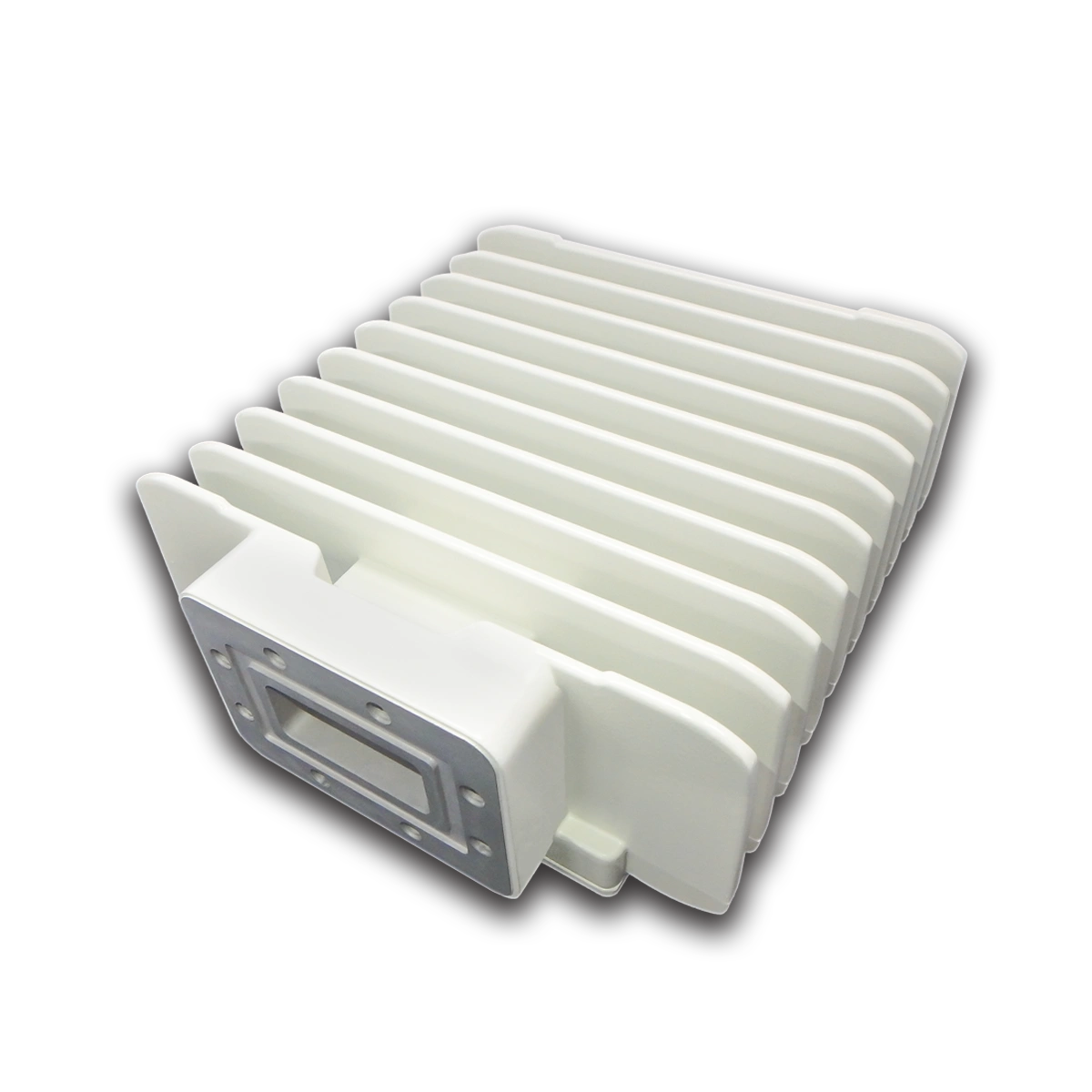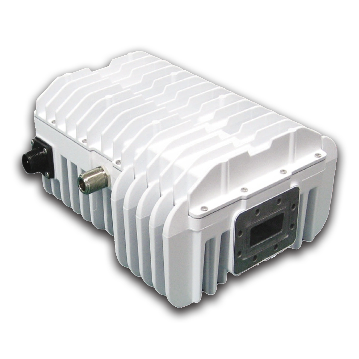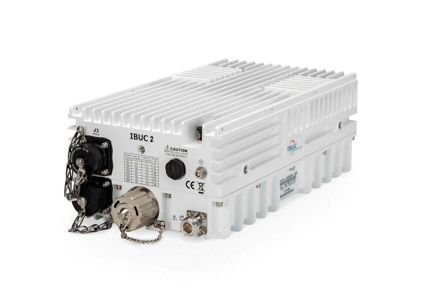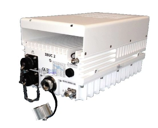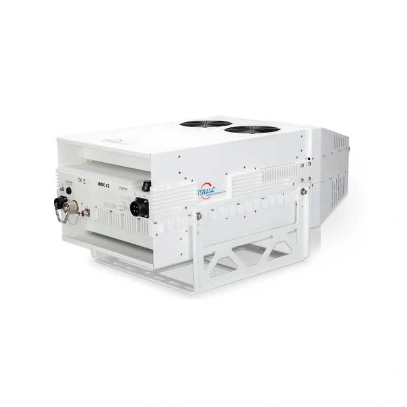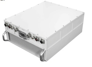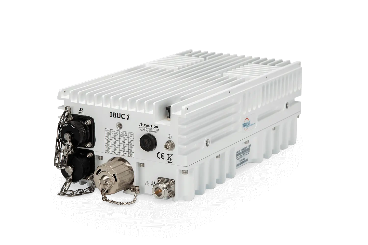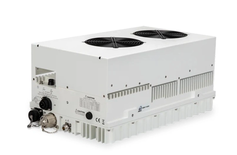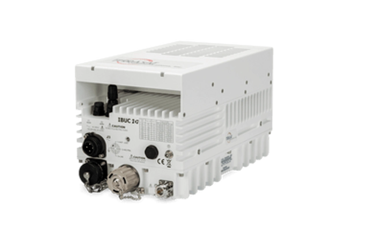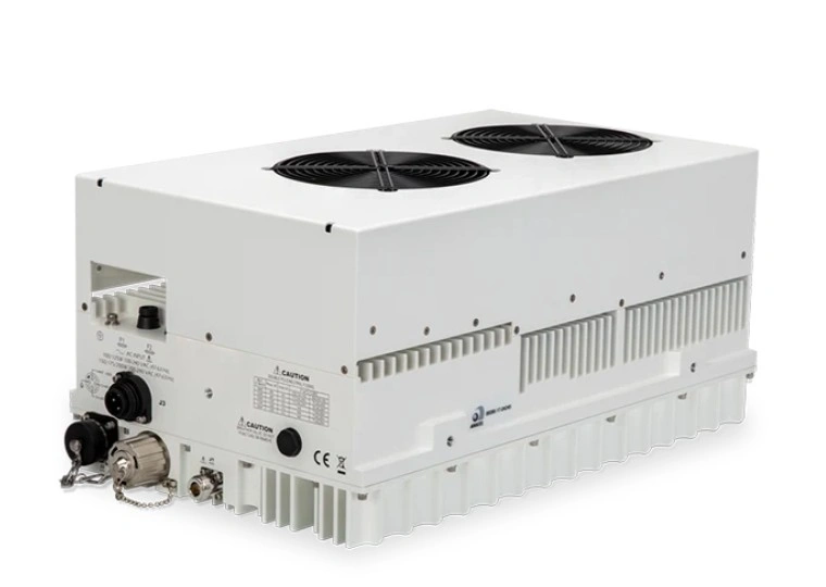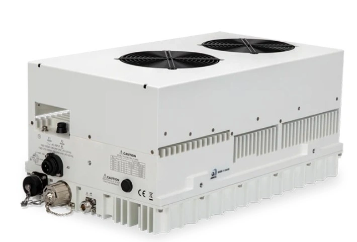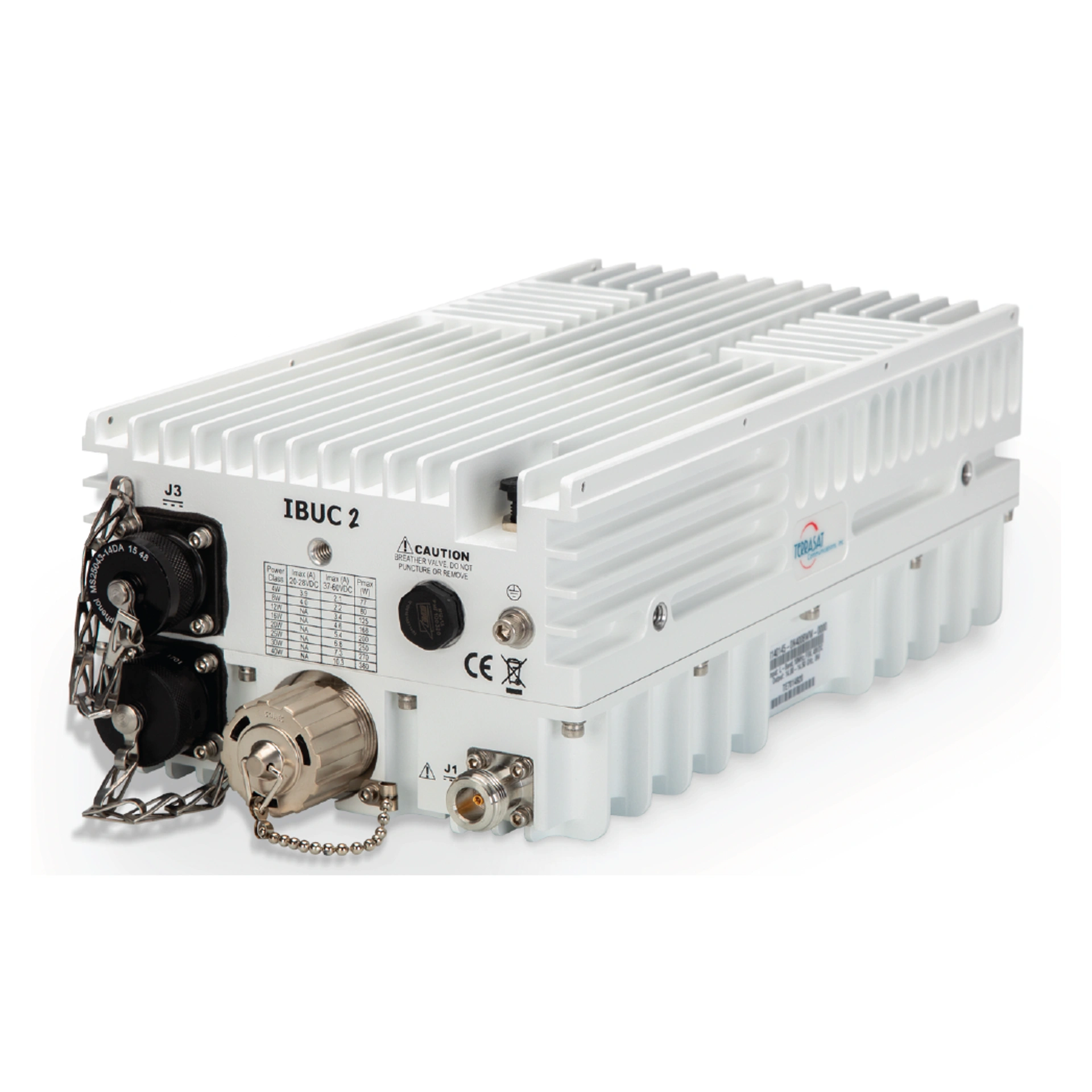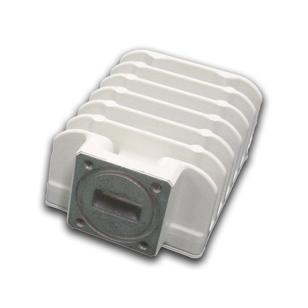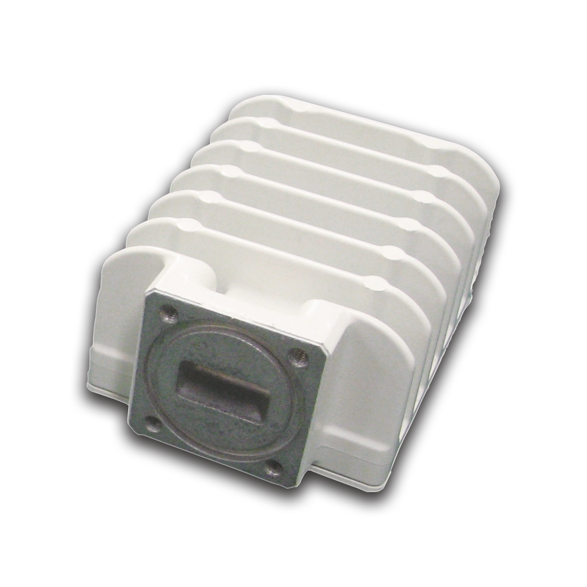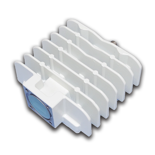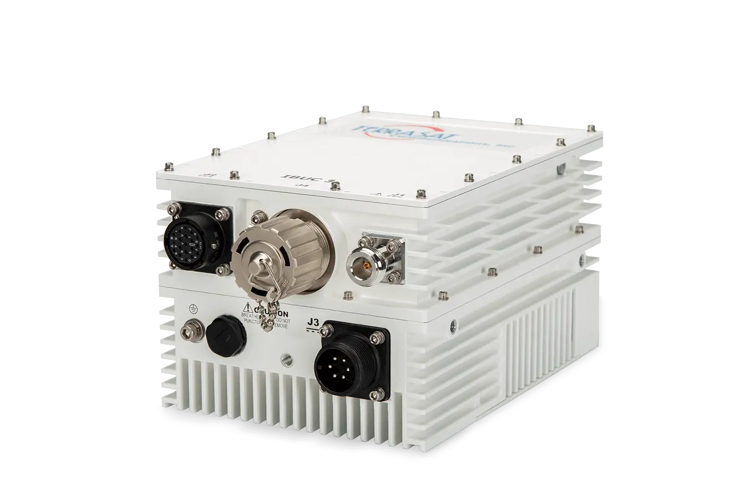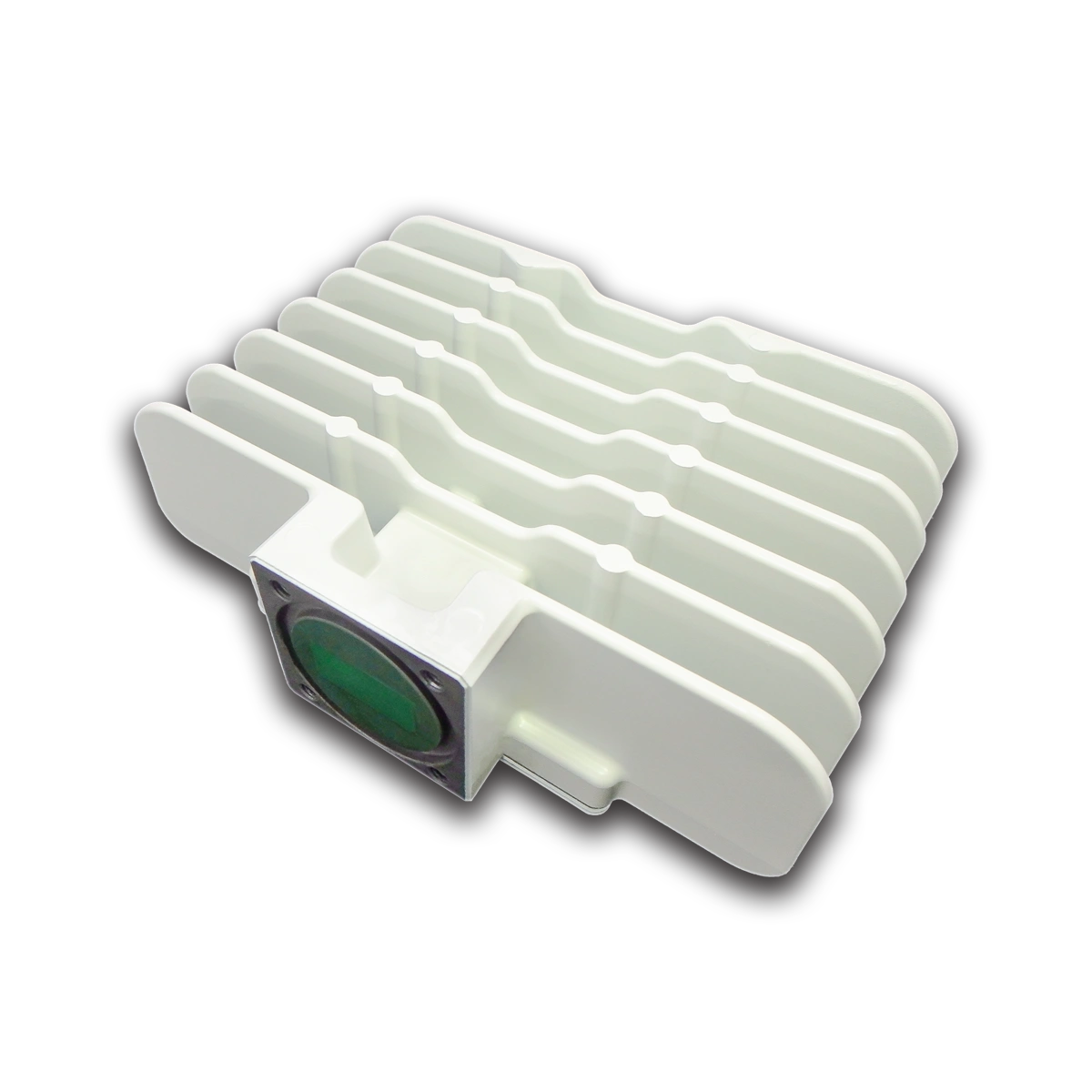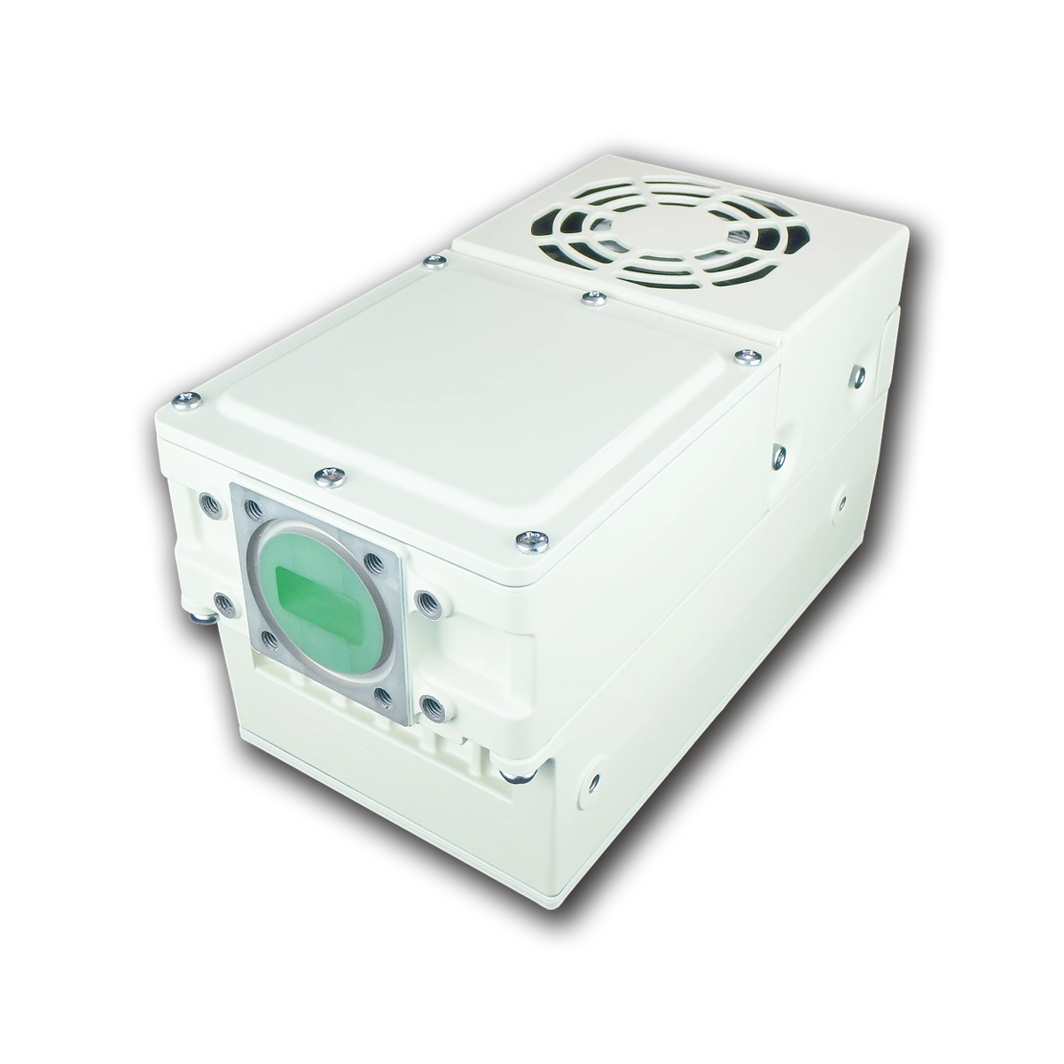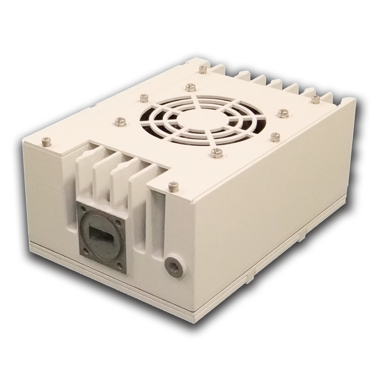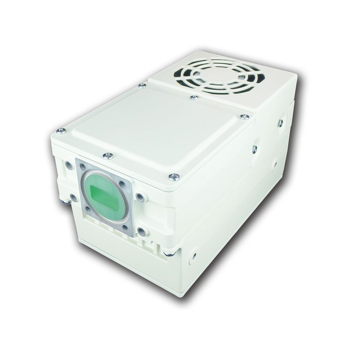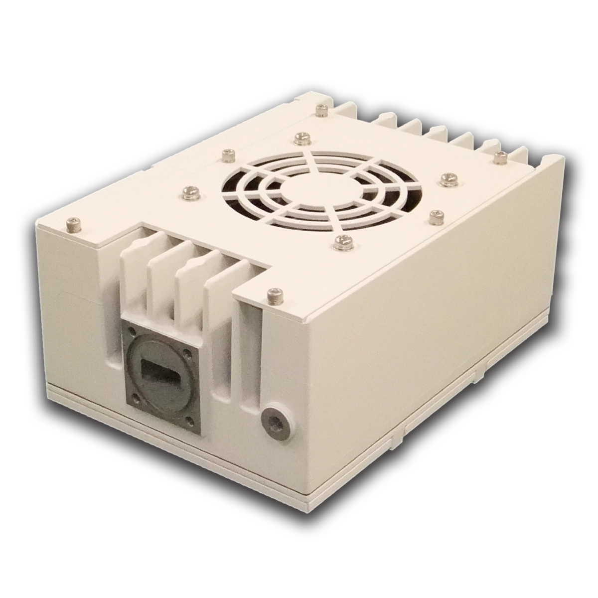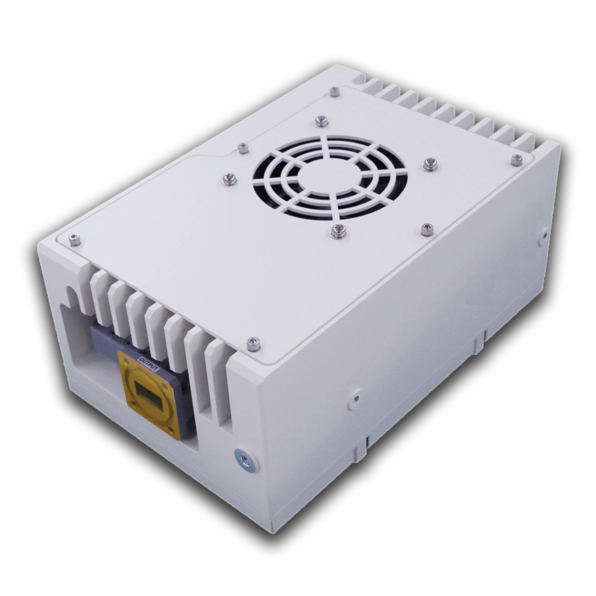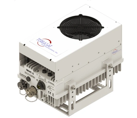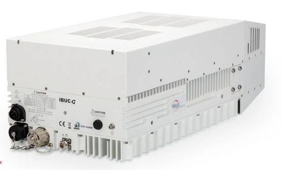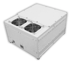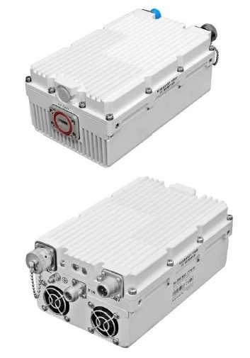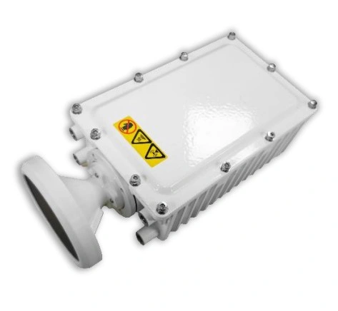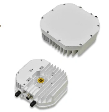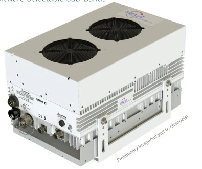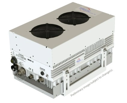










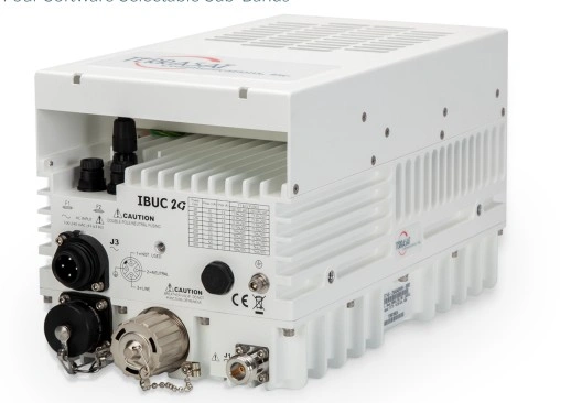
The IBUC 2G delivers proven superior performance in high data rate, & higher order modulation satellite links. With its rugged, compact design, the Ka-band IBUC 2G is suitable for both mobile & long-term fixed satcom terminals. GaN advantages include higher power in a smaller outdoor enclosure and low power consumption. Terrasat's unique implementation is designed for long lifetime performance in demanding environments. The Quad-Band version includes selectable multiband controls for multicarrier transmissions, deploying high versatility for your SATCOM terminals, and universal range in the Ka-band spectrum. Multiple sensors & a new, high-capacity microprocessor provide tools to optimize remote terminal performance. The IBUC 2G is a popular choice for satcom uplinks for telecom, government, defense and other demanding applications.
- Highest quality & exacting performance guaranteed through individual unit testing over temperature
- Superior linearity for maximum useable output power
- Amplifier overdrive protection
- User-selectable AGC/ALC for optimal performance & compatibility with modem adaptive coding
- New high capacity microprocessor & extended M&C functions
- Weatherized RJ45 Ethernet interface for simplified connection
| RF Parameter | Specifications / Value | |
| RF Frequency Range (Universal Ka-Band) | 27.5 to 31.0 GHz (Divided into 4 Software-Selectable Sub-Bands) | |
| • Sub-band 1: 27.5 to 28.5 GHz | ||
| • Sub-band 2: 28.25 to 29.25 GHz | ||
| • Sub-band 3: 29.0 to 30.0 GHz | ||
| • Sub-band 4: 30.0 to 31.0 GHz | ||
| IF Frequency Range | 950 to 1950 MHz or 1.0 to 2.0 GHz (Any RF can be paired with any IF via software) | |
| Local Oscillator (LO) Frequencies | • Sub-band 1: 26.50 GHz / 26.55 GHz | |
| • Sub-band 2: 27.25 GHz / 27.30 GHz | ||
| • Sub-band 3: 28.00 GHz / 28.05 GHz | ||
| • Sub-band 4: 29.00 GHz / 29.05 GHz (Non-inverting) | ||
| • 20W Model: +43 dBm typ / +40 dBm min | |
| • 25W Model: +44 dBm typ / +41 dBm min | ||
| PSatcap P sub cap S a t end-sub | • 40W Model: +46 dBm typ / +43 dBm min | |
| • 20W: 74 dB min | |
| Small Signal Gain (WGS Version) | • 20W: 63 dB min | |
| Attenuator Range | 30 dB variable in 0.1 dB steps | |
| Gain Flatness | • Full Band: 4 dB p-p max for any Sub-Band | |
| • 54 MHz: 2 dB p-p max for any Sub-Band | ||
| Gain Variation Over Temp | • Open Loop: 4 dB p-p max | |
| Input VSWR & Impedance | 1.5:1 max / 50 Ohm (Type N Female) or 75 Ohm (Type F Optional) | |
| RF Output Interface & VSWR | WR28 UG Cover with Groove / 1.3:1 max | |
| 10 MHz, Level: -12 to +5 dBm (Multiplexed on TX IFL) | |
| SSB Phase Noise (External Ref.) | • 100 Hz: -63 dBc/Hz | |
| • 1 kHz: -73 dBc/Hz | ||
| • 10 kHz: -83 dBc/Hz | ||
| • 100 kHz: -93 dBc/Hz |