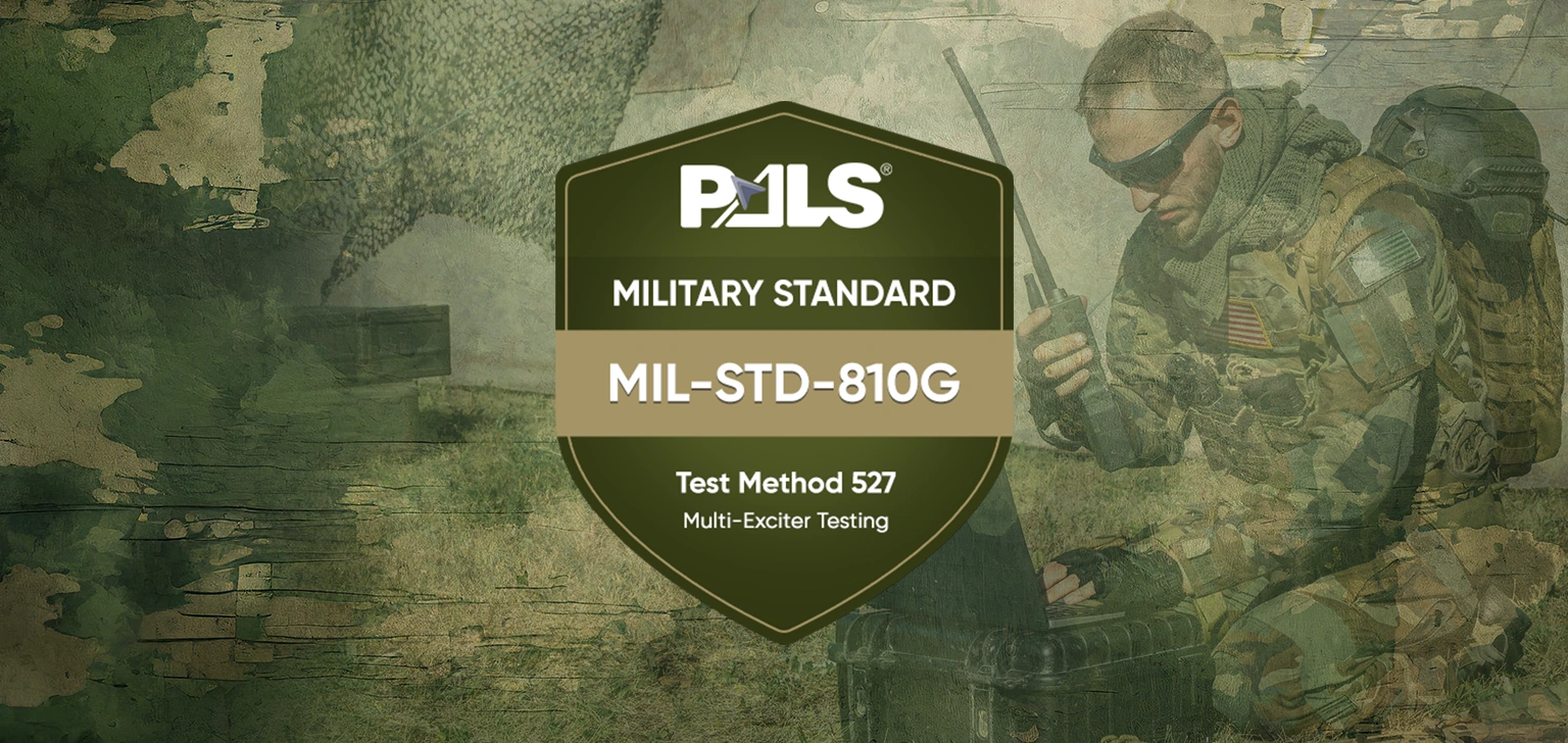


MIL-STD-810G Test Method 517.1 – Pyroshock
Pyroshock, also known as pyrotechnic shock, is the dynamic structural shock that occurs when an explosion or impact occurs on a structure. “Pyroshock” refers to the localized intense mechanical transient response of materiel caused by the detonation of a pyrotechnic device on adjacent structures. A number of devices are capable of transmitting such intense transients to a materiel. It is of particular relevance to the defense and aerospace industries in that they utilize many vehicles and/or components that use explosive devices to accomplish mission tasks. Examples include rocket stage separation, missile payload deployment, pilot ejection, automobile airbag inflators, etc. Of significance is the survival and integrity of the equipment after the explosive device has activated so that the vehicle can accomplish its task.
Test Method 517.1 – Pyroshock
Pyroshock tests involving pyrotechnic (explosive- or propellant-activated) devices are performed to:
- provide a degree of confidence that materiel can structurally and functionally withstand the infrequent shock effects caused by the detonation of a pyrotechnic device on a structural configuration to which the materiel is mounted.
- experimentally estimate the materiel's fragility level in relation to pyroshock so that shock mitigation procedures may be employed to protect the materiel’s structural and functional integrity.
Pyroshock usually exhibits no momentum exchange between two bodies (a possible exception is the transfer of strain energy from stress wave propagation from a device through the structure to the materiel). Pyroshock results in essentially no velocity change in the materiel support structure.
Image Courtesy: physicsclassroom
Pyroshock is a physical phenomenon characterized by the overall material and mechanical response at a structure point from either (a) an explosive device, or (b) a propellant-activated device. Such a device may produce extreme local pressure (with perhaps heat and electromagnetic emission) at a point or along a line. The device provides a near-instantaneous generation of local, high-magnitude, nonlinear material strain rates with subsequent transmission of high-magnitude/high-frequency material stress waves producing high acceleration/low velocity and short duration response at distances from the point or line source. The characteristics of pyroshock are:
• near-the-source stress waves in the structure caused by high material strain rates (nonlinear material region) propagate into the near-field and beyond;
• high frequency (100 Hz to 1,000,000 Hz) and very broadband frequency input;
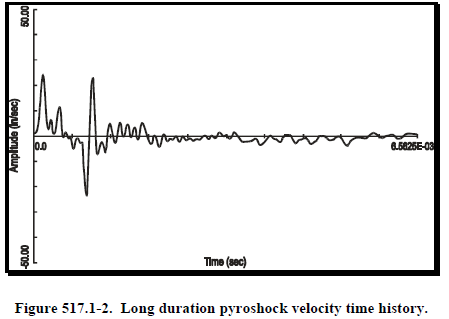
• high acceleration (300 g to 300,000 g) but low structural velocity and displacement response;
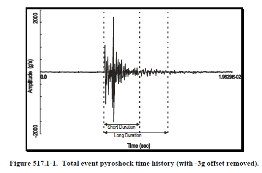
• short-time duration (< 20 msec);
• high residual structure acceleration response (after the event);
• caused by (1) an explosive device or (2) a propellant activated device (releasing stored strain energy) coupled directly into the structure; (for clarification, a propellant activated device includes items such as a clamp that releases strain energy causing a structure response greater than that obtained from the propellant detonation alone);
• highly localized point source input or line source input;
• very high structural driving point impedance (P/v, where P is the large detonation force or pressure, and v, the structural velocity, is very small). At the pyrotechnic source, the driving point impedance can be substantially less if the structure material particle velocity is high;
• response time histories that are random in nature, providing little repeatability and substantial dependency on the materiel configuration details;
• response at points on the structure that are greatly affected by structural discontinuities;
• materiel and structural response that may be accompanied by substantial heat and electromagnetic emission (from ionization of gases during explosion).
Classification Of Pyroshock Zones.
Procedures of this method are heavily based upon the definition of “near field”, “mid field” and “far-field” we would like to introduce you to these terms before we talk about procedures. The nature of the response to pyroshock suggests that the materiel or its components may be classified as being in the near-field, mid-field, or far-field of the pyrotechnic device. The terms “near-field,” “mid-field,” and “far-field” relate to the shock intensity at the response point, and such intensity is a function of the distance from the pyrotechnic source and the structural configuration between the source and the response point.
Near-field. In the near-field of the pyrotechnic device, the structure material stress wave propagation effects govern the response. A near-field pyroshock test requires frequency control up to and above 10,000 Hz for amplitudes greater than 10,000gs. A pyrotechnically excited simulation technique is usually appropriate, although in some cases a mechanically excited simulation technique may be used.
Mid-field. In the mid-field of the pyrotechnic device, the pyroshock response is governed by a combination of material stress wave propagation and structural resonance response effects. A mid-field pyroshock test requires frequency control from 3,000 Hz to 10,000 Hz for amplitudes less than 10,000gs. A mechanically excited simulation technique other than shaker shock is usually required.
Far-field. In the far-field of the pyrotechnic device, the pyroshock response is governed by a combination of material stress wave propagation and structural resonance response effects. A Far-field pyroshock test.
Procedures Of This Method Are As Follows:
Procedure I - Near-field with an actual configuration. Procedure I is intended to test materiel in its functional mode and actual configuration (materiel / pyrotechnic device physical configuration), and to ensure it can survive and function as required when tested using the actual pyrotechnic test device in its intended installed configuration. In Procedure I, it is assumed that the materiel or a portion of the materiel resides within the near-field of the pyrotechnic device.
Procedure II - Near-field with a simulated configuration. Procedure II is intended to test materiel in its functional mode but with a simulated structural configuration, and to ensure it can survive and function as required when in its actual materiel/pyrotechnic device physical configuration. In this procedure it is assumed that some part of the materiel lies within the near-field. Make every attempt to use this procedure to duplicate the actual platform/materiel structural configuration by way of a full-scale test. If this is too costly or impractical, employ scaled tests provided that in the process of scaling, important configuration details are not omitted. In particular, only the structure portion directly influencing the materiel may be involved in the test, provided it can be reasonably assumed that the remainder of the structure will not influence materiel response. On occasion, for convenience, a special pyrotechnic testing device may be employed for testing the materiel, e.g., a flat steel plate to which the materiel is mounted and the pyrotechnic charge is attached.
Procedure III - Mid-field with a mechanical test device. Replication of pyroshock for the mid-field environment with a mechanical device that simulates the pyroshock peak acceleration amplitudes and frequency content (other than an electrodynamic shaker because of frequency range and weight limitations of the electrodynamic shaker). Pyroshock can be applied using conventional high acceleration amplitude/frequency test input devices. Paragraph 6.1, reference b provides a source of alternative test input devices, their advantages, and limitations. In this procedure, it is assumed that all parts of the materiel lie in the mid-field of the pyrotechnic device.
Procedure IV - Far-field with a mechanical test device. Replication of pyroshock for the far-field environment with a mechanical device that simulates the pyroshock peak acceleration amplitudes and frequency content (other than an electrodynamic shaker because of frequency range and weight limitations of the electrodynamic shaker).
Procedure V - Far-field with an electrodynamic shaker. Replication of pyroshock for the far-field environment using an electrodynamic shaker to simulate the comparatively low frequency structural resonant response to the pyroshock. On occasion, pyroshock response can be replicated using conventional electrodynamic shakers. In this procedure, it is assumed that all parts of the materiel lie in the far-field of the pyrotechnic device, and the materiel is subject to the structure platform resonant response alone for frequencies less than 3,000 Hz.
Effects Of Pyroshock.
In general, pyroshock has the potential for producing adverse effects on all electronic materiel. The level of adverse effects generally increases with the level and duration of the pyroshock, and decreases with the distance from the source (pyrotechnic device) of the pyroshock. Durations for pyroshock that produce material stress waves with wavelengths that correspond with the natural frequency wavelengths of microelectronic components within materiel will enhance adverse effects. In general, the structural configuration merely transmits the elastic waves and is unaffected by the pyroshock. Examples of problems associated with pyroshock follow, but the list is not intended to be all-inclusive.
• materiel failure as a result of the destruction of the structural integrity of microelectronic chips;
• materiel failure as a result of relay chatter;
• materiel failure as a result of circuit card malfunction, circuit card damage, and electronic connector failure. On occasion, circuit card contaminants having the potential to cause short circuits may be dislodged under pyroshock.
• materiel failure as a result of cracks and fracture in crystals, ceramics, epoxies, or glass envelopes.
DID YOU KNOW?
PALS Electronics has experts on all subjects of test engineering, mechanical or electronic design, environmental condition engineer, system engineer, etc. PALS provides consulting, training, tailoring, test plan, test engineering, test services in all phases of your project. Please feel free if you have any questions or inquiries from https://pals.com.tr/contact