


MIL-STD-810G Test Method 521.3 – Icing and Freezing Rain
We will proceed to elaborate on the “Methods” and “Procedure”s of the environmental standard of MIL-STD-810 in our article series. Instead of writing down the obvious information already given in the standard, we will be discussing more practical information on product design, features regarding “Equipment Under Test” (EUT) and conducting tests.
Test Method 523.3 – Icing and Freezing Rain
The Icing and Freezing Rain test is conducted to evaluate the effect of icing on the operational capability of materiel. This method also provides tests for evaluating the effectiveness of de-icing equipment and techniques, including prescribed means to be used in the field. Ice formation can impede materiel operation and survival and affect the safety of operating personnel.
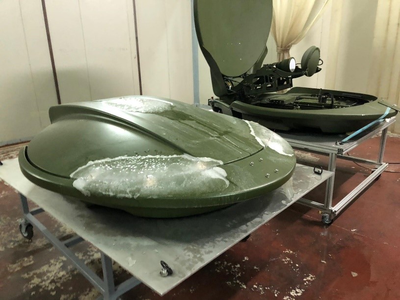
Photo: PDA-150-MIL Antenna while under Icing and Freezing Rain Test. From Left to Right, 37 mm operation and 6 mm storage. Ice accumulation was not completed when the photo was taken. For more info: https://pals.com.tr/product/pda-150-mil
Procedure of this method as follows:
This method has only one procedure. However, the test procedure may be varied. Before conducting this test, complete the tailoring process by selecting specific procedure variations (special test conditions/techniques for this procedure) based on requirements documents, Life Cycle Environmental Profile (LCEP). Please note following bullet-points are not procedures but the variations mentioned above. Variations applied to test subjects are heavily effects the pre-cautions that needs to be taken against.
• Ice Type (Accretion)
Two types of ice are commonly encountered: rime ice (opaque/granular) and glaze ice (clear/smooth). Published extremes for ice accretion may be used for calculating design and structural evaluations but are not considered practical for establishing test conditions due to the large thicknesses involved unless the test is intended to provide practical confirmation of design calculations. Rime is composed essentially of discrete ice granules and has densities ranging from 0.2 g/cm3 (soft rime) to almost 0.5 g/cm3 (hard rime).
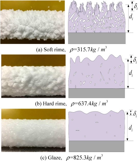
Photo: Laboratory induced Ice Types and their densities. Image Courtesy: Science Direct.
- Rime ice: A white or milky and opaque granular deposit of ice formed by rapid freezing of supercooled water drops as they impinge upon an exposed object. Rime ice is lighter, softer, and less transparent than glaze.
- Hard rime: Opaque, granular masses of rime deposited chiefly on vertical surfaces by dense, supercooled fog. Hard rime is more compact and amorphous than soft rime, and builds out into the wind as glazed cones or feathers. The icing of ships and shoreline structures by supercooled spray from the sea usually has the characteristics of hard rime.
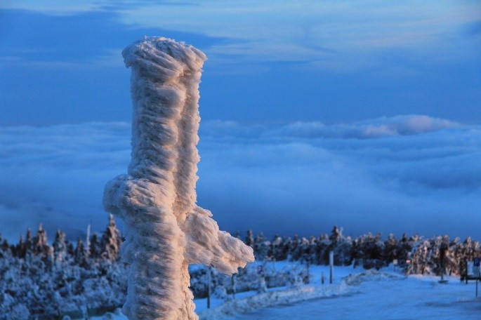
Photo: Naturally occurred Hard Rime Ice
b. Soft rime: A white, opaque coating of fine rime deposited chiefly on vertical surfaces, especially on points and edges of objects, generally in supercooled fog. On the windward side, soft rime may grow to very thick layers, long feathery cones, or needles pointing into the wind and having a structure similar to that of frost.
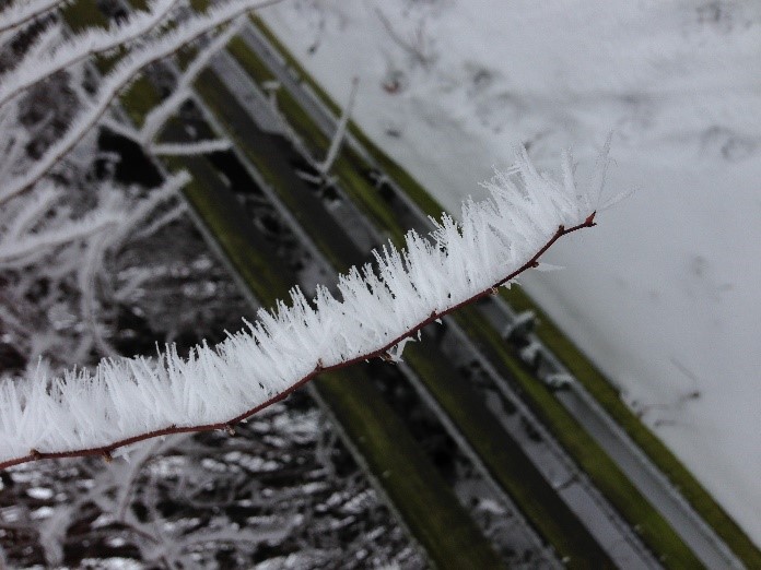
Photo: Naturally occurred Soft Rime Ice.
2. Glaze ice: A coating of ice, generally clear and smooth but usually containing some air pockets, formed on exposed objects by the freezing of a film of supercooled water vapor. Glaze is denser, harder, and more transparent than rime. Its density may range from 0.6 to 0.9 g/cm3. Factors that favor glaze formation are large drop size, rapid accretion, slight supercooling, and slow dissipation of heat of fusion. The opposite effects favor rime formation. Glaze occurs when rain or drizzle freezes on objects and is clear and nearly as dense as pure ice. Since glaze ice is more difficult to remove, it is structurally a more significant factor.

Photo: Naturally occurred Glaze Ice.
- Ice Thickness
a. 6mm (0.24 in) - represents general conditions, light loading.
b. 13mm (0.5 in) - represents general conditions, medium loading.
c. 37mm (1.5 in) - represents heavy ground loading and marine mast loading.
d. 75mm (3 in) - represents extremely heavy ground loading and marine deck loading.
Please note laboratory-induced ice thickness above 37 mm can carry an adult male’s weight. Naturally occurred 75 mm ice can carry an adult male.
Tips and Tricks;
• Information given above is purposed to explain the severity of situation. Please consider carefully EUT lifecycle and decide what circumstances may occur during EUTs service life.
• Please take operational considerations into account while preparing test plan. Some materiel covered with ice may be expected to operate immediately without first undergoing de-icing procedures; other materiel would not be expected to operate until some form of de-icing has taken place. (I.e. Washing aircraft with anti-freeze solution)
• Ice removal, if required, may include built-in ice-removal systems, prescribed means that could be expected to be employed in the field (such as removal of ice by ice scraper), or a combination of these.
• Please note pass and fail criterias are not defined in standard and leaved to define customer and manufacturer. Make sure what outcome should be expected. I.e. PDA-150-MIL antenna was expected to stay operational before-during-after the 6 mm of ice accumulation. Also expected to be operational only after (stored in) 37 mm ice accumulation. Both tests were conducted with built-in de-ice system with no human intervention to ice by any means.
• Use ice warning sticker in proper places on EUT in order to prevent personal footing injuries.
• Generally preventing water droplets to bind together and freeze is the key of the prevention of ice accumulation. This can be achieved by chemically, mechanically or manual ice prevention.
• Ice accumulation may have a heavy effect on moving parts by binding them together. Consider applying heating elements to joints if possible. If not consider force required to operate EUT under accumulation while choosing motor parts.
• Ice also can effect moving parts and motors by adding ice weight to them. Consider this weight and extra torque required to handle this weight during mechanical design phase. Computed Fluid Dynamics (CFD) analysis and Finite Element Response analysis is advised for this purpose.
• Adding small amounts of slopes (curves) to the wide affected surfaces of EUT can actually help to reduce icing by sliding them down. Just like the roof of the houses built in northern parts of globe.
• Ice can effect the electromagnetic transmission of antennas by changing electromagnetic flux and conductivity. There are many COTS solutions (heat blower, ice domes etc) as well as built-in heater options. In our example of PDA-150-MIL, Antenna system has hidden heating element on all reflecting surfaces which prevents disruption of communication in both operational and storage conditions.
DID YOU KNOW?
PALS Electronics has experts on all subjects of test engineering, mechanical or electronic design, environmental condition engineer, system engineer, etc. PALS provides consulting, training, tailoring, test plan, test engineering, test services in all phases of your project. Please feel free if you have any questions or inquiries from https://pals.com.tr/contact
by System Integration Engineer, Özdemir Öztürk