


MIL-STD-810G Test Method 516.6 – Shock
A mechanical or physical shock is a sudden acceleration caused, for example, by impact, drop Shock is a transient physical excitation. Shock describes matter subject to extreme rates of force with respect to time. Shock is a vector that has units of an acceleration (rate of change of velocity). The unit g (or g) represents multiples of the acceleration of gravity and is conventionally used.
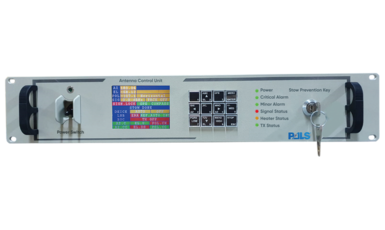
Video: Actual Footage of PDA-150-MIL Antenna under Shock Test
Test Method 516.6 – Shock
Shock tests are performed to:
- provide a degree of confidence that materiel can physically and functionally withstand the relatively infrequent, non-repetitive shocks encountered in handling, transportation, and service environments. This may include an assessment of the overall materiel system integrity for safety purposes in any one or all of the handling, transportation, and service environments;
- determine the materiel's fragility level, in order that packaging may be designed to protect the materiel's physical and functional integrity; and
- test the strength of devices that attach materiel to platforms that can crash.
Procedures of this Method are as follows:
Based on the test data requirements, determine which test procedure, combination of procedures, or sequence of procedures is applicable. In many cases, one or more of the procedures will apply. Consider all the shock environments anticipated for the materiel during its life cycle, both in its logistic and operational modes.
Procedure I - Functional Shock.
Procedure I is intended to test materiel (including mechanical, electrical, hydraulic, and electronic) in its functional mode and to assess the physical integrity, continuity and functionality of the materiel to shock. In general, the materiel is required to function during the shock and to survive without damage to shocks representative of those that may be encountered during operational service.
Procedure II - Materiel to be Packaged.
Procedure II is to be used when materiel will require a shipping container. It specifies a minimum critical shock-resistance level to a handling drop height. The shock definition may be furnished to a package designer as a design criterion. This procedure is not intended for the test of extremely fragile materiel, e.g., missile guidance systems, precision-aligned test equipment, gyros, inertial guidance platforms, etc. For extremely fragile materiel where quantification of shock resistance is required, consider Procedure III. See paragraph 2.3 below for processing techniques useful in expressing shock resistance criteria.
Procedure III - Fragility.
Procedure III is used to determine a materiel’s ruggedness or fragility so that packaging can be designed for the materiel, or so the materiel can be redesigned to meet transportation and/or handling requirements. This procedure is used to determine the critical shock conditions at which there is a reasonable chance of structural and/or functional system degradation. To achieve the most realistic criteria, perform the procedure at environmental temperature extremes. See paragraph 2.3 below for processing techniques useful in expressing shock fragility criteria.
Procedure IV - Transit Drop.
Procedure IV is intended for materiel either outside of or within its transit or combination case, or as prepared for field use (carried to a combat situation by man, truck, rail, etc.).
This procedure is used to determine if the materiel is capable of withstanding the shocks normally induced by loading and unloading when it is (1) outside of its transit or combination case, e.g., during routine maintenance, when being removed from a rack, being placed in its transit case, etc., or (2) inside its transit or combination case. Such shocks are accidental but may impair the functioning of the materiel. This procedure is not intended for shocks encountered in a normal logistic environment as experienced by materiel inside shipping containers (see Procedure II (Materiel to be Packaged) and Procedure VII (Pendulum Impact).
Procedure V - Crash Hazard Shock Test.
Procedure V is for materiel mounted in air or ground vehicles that could break loose from its mounts, tie-downs, or containment configuration during a crash and present a hazard to vehicle occupants and bystanders. This procedure is intended to verify the structural integrity of materiel mounts, tie-downs, or containment configurations during simulated crash conditions. Use the test to verify the overall structural integrity of the materiel, i.e., parts of the materiel are not ejected under the shock. This procedure is not intended for materiel transported as cargo for which Method 513.6, Acceleration, or Method 514.6, Vibration, could be applied. The crash hazard can be evaluated by a static acceleration test (Method 513 Procedure III) and/or a transient shock (Method 516 Procedure V). The requirement for one or both procedures must be evaluated based on the test item.
Procedure VI - Bench Handling.
Procedure VI is intended for materiel that may typically experience bench handling, bench maintenance, or packaging. It is used to determine the ability of the materiel to withstand representative levels of shock encountered during typical bench handling, bench maintenance, or packaging. Such shocks might occur during materiel repair. This procedure may include testing for materiel with protrusions that may be easily damaged without regard to gross shock on the total materiel. The nature of such testing is highly specialized and must be performed on a case-by-case basis, noting the configuration of the materiel protrusions and the case scenarios for damage during such activities as bench handling, maintenance, and packaging. This procedure is appropriate for medium-to-large test materiel out of its transit or combination case that has a maximum dimension greater than approximately 23 cm (9 inches). Small materiel systems, in general, will be tested to higher levels during Procedure IV, Transit Drop.
Procedure VII – Pendulum Impact.
Procedure VII is intended to test the ability of large shipping containers to resist horizontal impacts, and to determine the ability of the packaging and packing methods to provide protection to the contents when the container is impacted. This test is meant to simulate accidental handling impacts, and is used only on containers that are susceptible to accidental end impacts. The pendulum impact test is designed specifically for large and/or heavy shipping containers that are likely to be handled mechanically rather than manually.
Procedure VIII - Catapult Launch/Arrested Landing.
Procedure VIII is intended for materiel mounted in or on fixed-wing aircraft that are subject to catapult launches and arrested landings. For catapult launch, materiel may experience a combination of initial shock followed by a low-level transient vibration of some duration having frequency components in the neighborhood of the mounting platform’s lowest frequencies, and concluded by a final shock according to the catapult event sequence. For arrested landing, materiel may experience an initial shock followed by a low-level transient vibration of some duration having frequency components in the neighborhood of the mounting platform’s lowest frequencies.
Tips and Tricks;
• Advises given in this section will be mostly familiar with vibration test due to mechanical features and conduction methods of test. Although shock is rapid acceleration, it is a recommended read.
• Knowing what you are up against is prime prevention method for vibration. Read thoroughly the sections, annexes that which guide refers to you.
• It may take a lot of time to manufacture a test fixture. Ask electromechanical fixture details from your lab from the start. The Center of gravity of EUT mounted on fixture requires to be matched with the electromechanical shakers center of gravity to prevent damage to the electromechanical shaker. Your lab expert will be asking you to make revisions for your fixture design. After approval of your lab expert, you may manufacture the fixture. It is recommended to start this process as soon as you learned vibration test is required for your EUT.
• Acceleration sensors are used to determine as feedback to check if the shock is properly applied to EUT. These sensors are called control sensors. Therefore, sensor(s) numbers and positions on EUT has an important factors for gaining correct results. They are usually placed upon the connection interface between EUT and fixture.
• Monitor sensors may be available depending upon your laboratory’s inventory. They do not provide feedback for control. Their purpose is merely monitoring the shocks response from the surface they are placed upon. It is recommended to place these to the critical points on your EUT to get valuable data from test.
• It takes a lot of time and financial resources to conduct vibration test. The trial and error method is not feasible for many cases. In case of failure manufacturer will start over from the design and then manufacture of product adding a re-test to this equation to build a sum of financial resources of manpower, time, materiel. We recommend considering this test in the design phase by putting more hours into it. It may seem unnecessary at the first place but in case of failure this precaution will save the manufacturer a lot of resources
• Consider applying finite element analysis to your design. It will provide you with much valuable information about your design without even conducting tests. Each category has a graph and its table providing amplitude and frequency response of vibration on each axes. Use this information for simulating the same vibration environment.
• There is an extensive selection of shock and vibration absorbers in market. Some of the manufacturers are even able to provide their vibration response data of their product. Or CAD data to designer make analysis.
• Consider using composite material for manufacturing large parts because of its advantage of elasticity.
• Use helical washers along with flat washers. They will apply enough pressure to bolts and screws preventing self unscrewing.
• Apply your favorite brand thread locking fluid but chose the proper one. They are color-coded according to their resistance.
DID YOU KNOW?
PALS Electronics has experts on all subjects of test engineering, mechanical or electronic design, environmental condition engineer, system engineer, etc. PALS provides consulting, training, tailoring, test plan, test engineering, test services in all phases of your project. Please feel free if you have any questions or inquiries from https://pals.com.tr/contact
by System Integration Engineer, Özdemir Öztürk