


MIL-STD-810G Test Method 514.6 – Vibration
We will be elaborating Vibration Test Method this week. It is an extensive subject in both aspects of conduction of test (Methods) and EUT (Tips and Tricks) as well. Although it would be hard to cover all these methods within a few minutes of read as we always do, we will try to cover the essence for each matter. So the reader can apply it to their own EUT.
Video: Actual Footage of PDA-150-MIL Antenna under Vibration Test
Test Method 514.6 – Vibration
Vibration tests are performed to:
a. Develop materiel to function in and withstand the vibration exposures of a life cycle, including synergistic effects of other environmental factors, materiel duty cycle, and maintenance. This method is limited to consideration of one mechanical degree-of-freedom at a time.
b. Verify that materiel will function in and withstand the vibration exposures of a life cycle.
Video: Actual Footage of PAC-550-MIL Antenna Controller under Vibration Test
Selection of Life Phase, Platform, Category and Test Procedure:
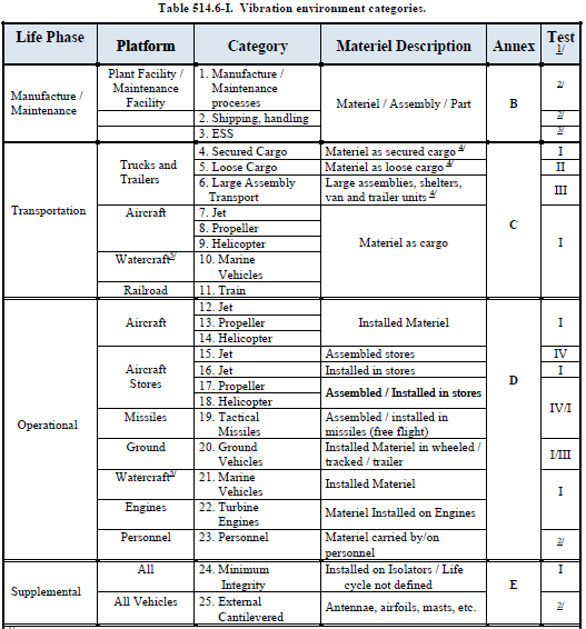
Although there are only 4 test methods for vibration tests, there are many vibration environmental categories (profiles) that can be applied in a combination with methods. The standard guides you through the selection of methods and environmental categories. We will follow the order in this guidance while covering this subject without overcomplicating it. Please note: the following table is taken from the standard itself. Our purpose is to help the reader to understand and interpret the table. Please keep in mind that "worst-case scenario" is the key thought process to selection and not any less of "worst-case scenario".
Life Phase Selection
Selection of method starts with which Life Phase of EUT will be tested. One or more Life Phase can be selected depending of EUT’s environmental life cycle. In other words, what can or will happen during EUT’s life.
• Manufacture / Maintenance: All materiel will experience some vibration during manufacture and maintenance. When different serial number items (lots) experience significant differences in vibration exposure during manufacture; selection of vibration test specimens, exposure levels, and exposure durations from those lots that experience the maximum vibration exposure.
It is suggested by standard to measure manufacturing (I.e. Caused by line conveyor), Shipping / Handling (of subassemblies) vibrations whenever possible, and extract the vibration profile. Then take it into account while in the design phase.
• Transportation: Vibration will likely happen to EUT while it is in transport (Note that it’s different from shipping or handling). Transportation is meant of the finished product. It is important which vehicle is used for transportation for choosing category. Also please keep in mind how EUT is transported matters as well. These tests are conducted while EUT is in transportation configurations. For example, some materiel is transported in it’s case, box, etc. Then the test will be done while EUT is in its case, box, etc.
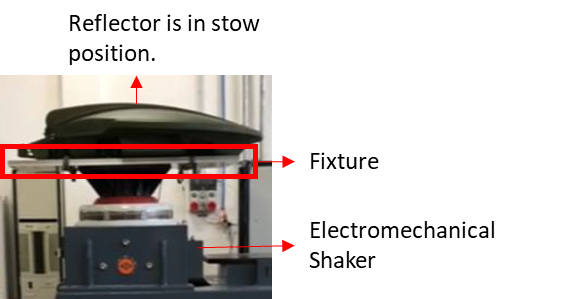
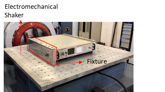
You will be hearing a lot about fixtures from this point. We would like to explain what is a fixture is with a real-life example. PDA-150-MIL antenna is transported and mounted on top of a ground vehicle. A fixture for EUT specifically designed and manufactured to simulate the PDA-150-MIL antenna's real working environment. The fixture was simulating ground vehicle in this case. Satellite antenna mounted on top of this fixture as the exactly same number and size of bolts is while being tested for transportation vibration.
Another most used word is test item configuration. From the same example of PDA-150-MIL satellite antenna is in stow position (antenna reflector is down) while ground vehicle goes from point A to point B. Therefore transportation vibration tests were conducted while antenna reflector is stowed.
Picture: Actual Photo of PDA-150-MIL Antenna while Vibration Test
• Operational: This section applies to materiel installed in a vehicle, aircraft store, turbine engine, or carried by personnel. Such materiel may be permanently installed or removable. If we elaborate on the subject: the question is whether if EUT will be operated while under vibration. I.e. if the vehicle is moving while EUT is operated.
If we follow the same pattern for giving an example of PALS products, PAC-550-MIL antenna controller is expected to be operated while the ground vehicle is moving. So it will be in it operational test item configuration while being tested. Meaning powered on, and all features are expected to be working.
PAC-550-MIL is a rack-mounted device. A fixture simulating PAC-550-MIL mounted on the rack is specially designed and manufactured for this test.
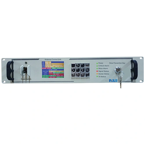
Picture: Actual Photo of PAC-550-MIL Antenna Controller while Vibration Test
• Supplemental: Minimum Integrity Test (MIT) methods are generally relatively unsophisticated tests that can be adopted when a precise simulation is not necessary to establish suitability for service. These are normally coupled to generalized or fallback test severities which may be used in the earlier phases of a materiel development program when adequate information may not be available to allow the use of project-specific severities. The MIT test category is still employed and, therefore, continues to be included within the MIL-STD-810 guidelines; however, it is placed under the category “supplemental” due primarily to the unorthodox non-tailored nature of the test category with advice to implement with care.
Platform and Category Selection
After the designation of Life Phase, Platform type should be chosen according to the real-life installation of EUT. By real life means which vehicle, where EUT is installed, and how EUT is installed matters while the selection of methods, which we covered them in the previous section.
Platform names such as Aircraft, Watercraft, Ground vehicle, Truck, Railroad, or Carried on/by Personnel are pretty self-explanatory.
Instead of explaining categories one by one, it would be much more helpful to learn for the reader to understand how to decipher them. All categories consist of one graph and table. Category 4 is chosen by the author because it was one of the categories applied to PDA-150-MIL antenna and the Category 4 graph and table will be explained in this section.
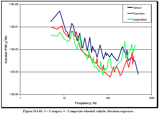
This figure is a graphic interpretation of vibration exposure-response for humans to understand. This figure taken from standard.
Vertical axis represents the amplitude of force and the horizontal axis is the frequency of force applied.
Colors are representing axes of force applied. Since real-world consists of 3 axes, vibration tests are conducted in 3 axes as well. Unless otherwise specified, the test applied one axis at a time. Since this figure representation of 3 axes on a 2D graph, it may look hard to read. You may take a look at the following picture for a better understanding of axes. Please note Category 4 is for Transport Phase, Truck Vehicle, Secured cargo hence picture is chosen accordingly.
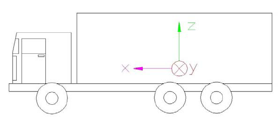
Picture: Representation of Longitudinal (X), Transverse (Y, towards to reader while looking at screen) and Vertical (Z) axes on a Truck.
Table: Vibration amplitude corresponding frequency for each axes.
Selection of Annex and Procedures
If you reached at point where selecting the proper Life Phase, Platform, and Category, Guide is given in standard leads you to Annex number. You will obtain valuable information by reading referenced annex thoroughly. Such as duration of exposure (test duration). I.e. Catergory 4 test duration is 60 minutes for common Truck. Please note duration is for one axis only. Therefore 60 minutes of test should be conducted in all axes. Meaning total 3 hours of vibration to the same EUT without preparation and pre-test time.
In final step, guides refers to you proper test procedure should be applied to the EUT. Procedures of this Method are as follows:
Procedure I – General Vibration. is for materiel to be transported as secured cargo or deployed for use on a vehicle. This procedure applies to ground vehicles as well as fixed and rotary-wing aircraft. For this procedure, the test item is secured to a vibration exciter, and the vibration is applied to the test item as an input at the fixture/test item interface. Steady-state or transient vibration may be applied as appropriate.
Procedure II - Loose Cargo Transportation. Is for materiel to be carried in/on trucks, trailers, or tracked vehicles and not secured to (tied down in) the carrying vehicle. The test severity is not tailorable and represents loose cargo transport in military vehicles traversing rough terrain.
Procedure III – Large Assembly Transportation. is intended to replicate the vibration and shock environment incurred by large assemblies of materiel installed or transported by wheeled or tracked vehicles. It is applicable to large assemblies or groupings forming a high proportion of vehicle mass, and to materiel forming an integral part of the vehicle. In this procedure, use the specified vehicle type to provide the mechanical excitation to the test materiel. The vehicle is driven over surfaces representative of service conditions, resulting in a realistic simulation of both the vibration environment and the dynamic response of the test materiel to the environment. Generally, measured vibration data are not used to define this test. However, measured data are often acquired during this test to verify that vibration and shock criteria for materiel subassemblies are realistic.
Procedure IV – Assembled Aircraft Store Captive Carriage and Free Flight. is to fixed-wing aircraft carriage and free flight portions of the environmental life cycles of all aircraft stores, and to the free flight phases of ground or sea-launched missiles. Use Procedure I, II, or III for other portions of the store’s life cycle as applicable. Steady-state or transient vibration may be applied as appropriate. Do not apply Procedure I to fixed-wing aircraft carriage or free flight phases.
Tips and Tricks;
• There are 25 categories and their procedures in standard. We tried to cover essentials by how to read and decipher them. Please keep in mind PALS offers their expertise on the subject. You may reach to us if you have any questions.
• Knowing what you are up against is prime prevention method for vibration. Read thoroughly the sections, and annexes that which guide refers to you.
• It takes a lot of time and financial resources to conduct vibration test. Trial and error method is not feasible for many cases. In case of failure manufacturer will be start over from the design then manufacture of the product adding re-test to this equation to build a sum of financial resources of manpower, time, materiel. We recommend taking this test into consideration in the design phase by putting more hours into it. It may seem unnecessary at first place but in case of failure this precaution will save the manufacturer a lot of resources
• Consider applying finite element analysis to your design. It will provide you much valuable information about your design without even conducting tests. Each category has a graph and its table providing amplitude and frequency response of vibration on each axes. Use this information for simulating the same vibration environment.
• There are extensive selection of shock and vibration absorbers in the market. Some of the manufacturers are even able to provide their vibration response data of their product. Or CAD data to designer make analysis.
• It may take a lot of time to manufacture test fixture. Ask electromechanical fixture details from your lab from the start. The Center of gravity of EUT mounted on fixture requires to be matched with the electromechanical shakers center of gravity to prevent damage to the electromechanical shaker. Your lab expert will be asking you to make revisions for your fixture design. After approval of your lab expert, you may manufacture the fixture. It is recommended to start this process as soon as you learned vibration test is required for your EUT.
• Consider using composite material for manufacturing large parts because of its advantage of elasticity.
• Use helical washers along with flat washers. They will apply enough pressure to bolts and screws preventing self unscrew.
• Apply your favorite brand thread locking fluid but chose the proper one. They are color-coded according to their resistance.
DID YOU KNOW?
PALS Electronics has experts on all subjects of test engineering, mechanical or electronic design, environmental condition engineer, system engineer, etc. PALS provides consulting, training, tailoring, test plan, test engineering, test services in all phases of your project. Please feel free if you have any questions or inquiries from https://pals.com.tr/contact